Theory of Operation
Mixer
The mixer design is a simple inverting summing opamp configuration. I've also included the clipping diodes for an optional distorted output, following Moritz Klein's design (ref. 1).
Attenuverter
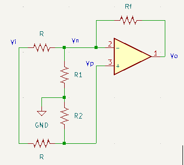
Voltage divider R1-R2 is implemented with a fixed R (R_1') in series with a variable resistor (pot) with max R R_2'.
\begin{aligned}
0 &= \frac{V_p - V_i}{R} + \frac{V_p}{R_2} \\
\to V_p &= \frac{R_2 V_i}{R_2 + R}\quad\mathrm{with}\quad V_p = V_n \\
0 &= \frac{V_n - V_i}{R} + \frac{V_n}{R_1}+\frac{V_n-V_o}{R_f} \\
\to 0 &= V_n - V_i + \frac{R}{R_1}V_n + \frac{R}{R_f}V_n - \frac{R}{R_f}V_o \\
\to \frac{R}{R_f}V_o &= V_n\left(1 + \frac{R}{R_1} + \frac{R}{R_f}\right) - V_i \\
\to \frac{R}{R_f}V_o &= \left[\frac{R_2}{R_2 + R}\left(1 + \frac{R}{R_1} + \frac{R}{R_f}\right) - 1 \right]V_i \\
\mathrm{let}\ R_f &= R \\
\to V_o &= \left[\frac{R_2}{R_2 + R}\left(\frac{2R_1 + R}{R_1}\right) - 1 \right]V_i
\end{aligned}
If R_2=0 (potentiometer wiper is set to the end stop), V_o = -V_i . Choosing the maximum potentiometer value to be R_2'=R and the remaining fixed resistance R_1=R_1'
\begin{aligned}
2 &= \frac{R_2}{R_2+R}\left(\frac{2R_1 + R}{R_1}\right) = \frac{R}{2R}\left(\frac{2R_1' + R}{R_1'}\right) \\
\to 4R_1' &= 2R_1' + R \to R_1' = \frac{1}{2}R
\end{aligned}
References
- Moritz Klein, "mki x es.edu Mixer" [ericasynths.lv]
- "Dual Atenuverter", Befaco [befaco.org]
- Horowitz and Hill, "The Art of Electronics", 3rd ed. Cambridge University Press, NY, 2015