Design
Overview
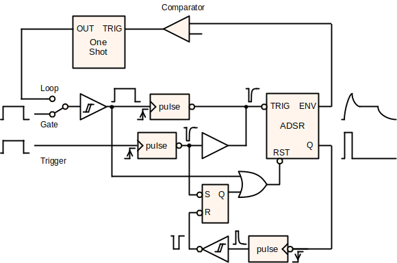
The module is designed around the 555-core ADSR. The input to the ADSR core is a logic-high pulse with length T. The rising edge of this pulse is converted to a short, inverted trigger to start the envelope. The pulse itself also holds the (active-low) reset high, which generates the window for the attack, decay & sustain phases. When the gate pulse is removed, the release phase is triggered.
When the external gate is selected, a Schmitt-trigger buffer converts the input signal into a pulse. Alternatively, the EG can be switched into a looping mode: a comparator detects the end of the envelope (release decays below ~100mV) and triggers a one-shot, which provides an adjustable-length gate pulse.
A trigger input can also be used to initiate the attack phase of the envelope. The trigger can arrive at any time and will cause the envelope to reach its peak in the attack phase before entering the decay or release phase depending on the state of the gate.
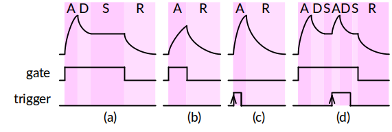
Examples of envelope sequences are illustrated below.
- A typical envelope. After the attack (A) and decay (D) the envelope remains at the sustain (S) level until the gate is removed, then drops to 0 during the release (R) phase.
- When the gate is removed before the attack phase is complete, the envelope will immediately enter the release phase and the envelope will not reach its maximum.
- When a trigger is applied, the length of the trigger pulse is ignored. A complete attack phase (envelope to maximum) occurs before the release phase.
- A trigger can be applied during an envelope to start a new attack phase. The envelope will reach its maximum before returning to the sequence depending on the state of the gate signal.
Subcircuits
There are more detailed design notes on the following subcircuits:
The analysis of the 555-core EG is covered in the original design references.
Notes on Features
"Why do it this way?"
Off State
The original variants don't really decay back to 0V in the off state. Between the small signal diodes and the VCE of the input buffer, I could only get it to about 200mV. The only discussion I found on this was on Eddy Bergman's site (thank you), and is resolved with precision diode implementation in the Kassutronics version (very clever). Eddy Bergman came up with a partial fix by switching to Schottky diodes, which could be used to free up another opamp, but concludes that the precision diode version (Kassutronics) is better.
The Extra Opamp
Rene Schmitz's version uses two OPAs (nicely satisfied with a TL072). Later designs (YuSynth+) added an inverting output (also nicely featured in Moritz Klein's non-555 version), but that leaves one more...
- Blink an LED (YuSynth, Kassutronics). In my opinion, better replaced with a BJT (see Moritz Klein's version), but the Kassutronics version neatly combines the inverting and blinking and uses the other for the precision diode.
- Loop trigger (Moritz Klein). In combination with the precision diode for the release path, I had to give up the inverting output.
- Inverted output. This comes in a few forms, but the attenuverter stage is probably the most flexible. I liked the way that Moritz Klein did it with the offset, giving an inverted control signal, e.g. for a "normally open" filter.
More details for the Loop Comparator can be found on that page.
Decay vs. Release
When the gate is removed before the decay completes, Yves Usson added a MOSFET to force the capacitor to discharge through the release path. Fancy.
Various Input Stages
Generally, a combination of Schmitt-trigger buffer and edge-triggered pulse generator are used, but the details change from design to design. I tried a classic Schmitt trigger (see Kassutronics or YuSynth), but was concerned that it would hold up the off-state voltage (before I found the precision diode design) and went back to Rene Schmitz's buffer. Unfortunately, that buffer can latch up, so in the new version with the trigger input, I've adopted the Schmitt-trigger buffers again. More detailed design notes for the Input Buffer are found on that page.
Manual Gate
This is an easy addition, see e.g. Kassutronics.
(Re-)Triggering
There's some discussion about how no true ~~Scotsman~~ musician could do without a re-triggerable ADSR. This makes some sense for pianos (think "sustain pedal"). This was the main motivation for the second version of this design, and I was able to incorporate a trigger with some additional buffers and an SR latch based on the CD4093 quad NAND gate.
Other Variants
There are some other interesting design ideas out there that I found while investigating the design of this ADSR.
Befaco VC ADSR
- befaco.org
- Discrete logic based ADSR sequence (latches & flip-flops)
- voltage control on all stages
- switch between gate and trigger mode
- shape-controllable between exponential and linear rise and fall.
MFOS (Ray Wilson) ADSR Envelope Generator
- musicfromouterspace.com
- discrete logic based ADSR sequence (latches)
- re-triggerable A+D/R