Mixer+
Continuing on the migration and clean-up of my modules, I refreshed the Mixer+ design and documentation. This was a more involved effort: I populated a second copy of the v1.1 PCB for my "production" case, and while I was doing that I ran into some issues.
Mixer+ was based on Moritz Klein's design (in particular the inspiration for the diode-clipped output). I added a few utility pieces (attenuverter & offset), which have come in handy developing and testing other modules. I found the 2-LED level indicator on one of the Befaco designs, but simplified it a bit. This was one of the first designs I worked on as I found I needed more utility modules to help design and test the more musical modules that come later.
I've noticed that building a second board is almost harder than the first. There's lots of opportunity to second guess component choices, and I've run into bugs that didn't seem to show up in the first build. That was the case with Mixer+: when I started testing, the non-inverting output was clipping heavily and the high-level output indicator (the red LED) wasn't lighting up. Combined with the fact that I didn't keep a clear record of changes (does the schematic really match the board?), the location of the issue made it hard to debug.
This is what I saw on the scope (the gain is designed so that an individual channel can be passed with unity gain, so it should match the input):
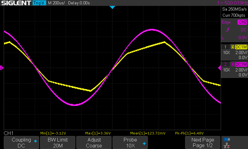
Here's what I think happened: I used a different (better?) 10u capacitor for the rectifier. With no additional resistance in series beteween the diode and the cap, the current would spike. This current in turn killed the diode, so instead of rectifying the output, the output opamp would end up reaching its current limit, which led to the ramp behaviour in the clipped output signal.
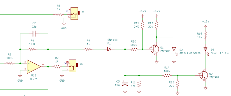
It took a long time (and many dead end paths) to find this, but adding a 1k series resistor (R9) and replacing the diode (D1) seems to have resolved the problem. I made that change with a bodge on the v1.1 board, but updated the v1.2 schematic and PCB with this fix.